
How a Team Verifies LOD Before a Scan to BIM Handover
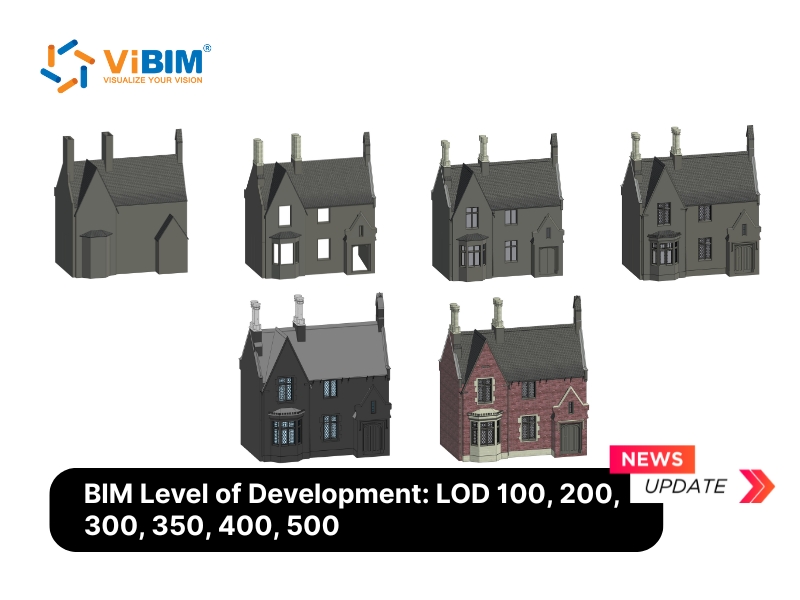
Handover day is when a vague LOD agreement gets expensive. A model arrives, the contractor opens it, and someone asks whether the pipes above the ceiling are really where the file says they are. This walkthrough follows the checks a team can run so that question is answered before the model leaves the building.
Step 1: Read the matrix, not the label
Level of Development is assigned element by element, so the first job is to open the LOD matrix in the BIM Execution Plan and list what each element group is supposed to support. A door that serves layout needs a generic placeholder. The same door needs its measurable width, height, vision panel and swing direction when a contractor coordinates the opening, and sill, frame trim and assembly detail when a supplier must fabricate it. Reading the matrix first stops the team from judging a model by how good it looks, because Level of Detail and Level of Development are different things.
Step 2: Compare the model to the scan
A model can look polished and still fail here. Teams that rely on point cloud to BIM services overlay the finished model on the registered scan and measure the gap element by element against the agreed tolerance, which on real projects is set at values such as 2 in (50 mm), 1.2 in (30 mm) or 0.6 in (15 mm). Coverage gaps, low point density and hidden surfaces show up at this stage. Where the scan cannot support the target level, the options are supplementary measurements, a denser rescan or a lower target LOD.
Step 3: Separate seen from assumed
A laser scan records only the surfaces it can see. Pipes behind finishes and structure above ceilings are often modeled by interpolation, so they cannot be called LOD 500 until they are field-verified or carry a stated accuracy. The verification list should therefore split elements into observed, interpolated and verified, and attach the accuracy statement to each group.
Step 4: Check the interfaces
At LOD 350, an element also has to show how it meets its neighbours. The reviewer checks hangers, supports and connections on exposed services, and confirms that trades meeting at a junction no longer clash in the coordination model. At LOD 300 this step is not required, which is a good reminder to check the level before judging the geometry.
Step 5: Check the information, not just the shape
An LOD 300 pipe can have a measurable size, shape, location and orientation without carrying product or maintenance data. If facility management needs supplier and maintenance fields, those belong to the Level of Information and must be listed in the handover requirements next to the observed geometry.
A real-world reference point
ViBIM's guide to BIM level of development describes three delivered projects that used LOD 200, 300 and 350. The train station was modeled at LOD 200, the factory at LOD 300 and matched to the scan within 0.6 in (15 mm), and an aluminum extrusion press at LOD 350 with a required accuracy of ±0.25 in (6 mm).
Closing checklist
- The matrix states a level for every element group.
- The model has been compared with the registered scan at the agreed tolerance.
- Interpolated elements are labelled and not claimed as LOD 500.
- Interfaces are checked wherever LOD 350 is specified.
- Information requirements are listed apart from geometry.
Run these five checks and the handover conversation changes from "can we trust this?" to "here is exactly what you can trust, and how far."