
From Scan to Signed-Off Revit Model: How a Conversion Gets Verified
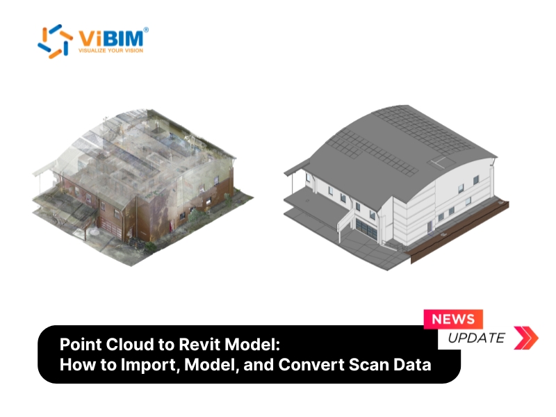
Most conversations about turning scan data into a Revit model focus on the modeling. The part that decides whether a team can trust the result is the verification, and it starts earlier than people expect.
Picture a registered scan arriving from a survey provider. Before anyone draws an element, the intake check looks for three things: duplicate points, misaligned scan patches and areas with no coverage. Anything suspicious goes back to the scanning provider for confirmation. Modeling on a flawed cloud only moves the error into the model, where it is harder to find.
Next comes linking. Revit treats the cloud as an external reference, so the project file stays small while the points live on disk. The positioning choice made here, often Origin to Origin or Shared Coordinates depending on the client's coordinate spec, becomes the reference for every discipline. A quick measurement of one known dimension, such as a window opening, confirms position and scale before the real work begins.
Teams that deliver this kind of work for clients, including our own scan to BIM modelling services, tend to run modeling in a fixed order. Levels and grids come first, read from floor and ceiling surfaces. Architecture follows, then structure, then MEP, with the awkward geometry handled last. Every stage is traced over the cloud, one discipline at a time.
Then the verification begins. The first layer happens inside Revit. Paired sections cut through both the model and the cloud, one horizontal cut per level and vertical cuts along the two main axes of the building, through shafts, risers and plant rooms. Where the two disagree, the element is corrected, never the cloud. A cut through a window opening shows at once whether a modeled family has drifted from the scanned reveal.
The second layer happens in Navisworks. Linking the model and the cloud there surfaces the small things that are easy to miss in Revit, such as valves, minor equipment and lighting, and it shows how well the disciplines agree with each other. A pre-analysis tool flags missing items, alignment and tolerance issues, and the review is color-coded and zoned so that no area is skipped.
A final file-health pass closes the job. Naming is made consistent across views, families, types, materials and files. Levels, worksets and phases are checked, warnings are resolved and unused content is purged.
None of this removes the need for skilled modelers, because no tool yet decides on its own that one surface is a wall and another is a duct. Tolerance also follows the project specification and the quality of the scan, so the target is an agreed standard rather than one fixed number. Our write-up on how to convert point cloud to Revit model walks through the same sequence in more depth, from import to delivery.
The practical lesson is simple. Treat verification as part of the workflow from the first day, and the finished model becomes something a design or construction team can build from with confidence.