
From Tilted Columns to a Verified Model: How a Six-Floor Residential Scan Was Rebuilt
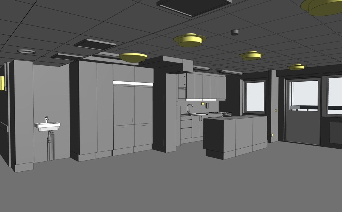
Every as-built project starts with a question: can the scan be trusted? On Project 561.EU, an apartment building in the European Union, the honest answer was "not completely". The building has five floors above ground and one basement, about 8,600 m² (92,570 sq ft), and ViBIM modeled it between October and November 2023.
Checking the data before modeling
The first step was to look at how the floors related to each other. The point cloud was poorly registered, particularly between the basement and the floors above. Columns and walls that should be vertical leaned, and nothing could be copied from one floor to the next.
The team asked the scanning firm for its registration report and for re-registration where the error was large. Then they chose the floor with the cleanest data, built one grid from it, and used section views across the main axes to line up every vertical element. That grid became the backbone of the whole model. Teams that offer as-built BIM modeling services rely on this kind of verification step, because a model built on a drifting scan carries the drift into every drawing.
Working through the basement
The basement scan was dark and cluttered with objects unrelated to the structure. Modelers filled the gaps with 360-degree and site photos so that columns, walls and services could be read with confidence.
Verifying as the model grows
With three disciplines in one Revit file, the team kept the work in small parts. They went room by room, moved sections through each room and compared the model with Matterport views. This made missing elements visible while the work was still in progress, rather than at final review.
The same discipline helped when the client asked, late in the job, to rotate Project North and change the base point. The model was too large to rotate at once, so it was split by discipline, MEP first among them, and every floor was checked again against the point cloud. The full story of the project is documented in this write-up of Revit modeling for a residential building in Europe, including the families and tools that kept the MEP work manageable.
Tools that made checks repeatable
An internal tool rounded family parameters, and an auto-rename tool applied the client's naming convention through a classification table. A custom family for vertical cable trays removed the need for workarounds. Client families that did not match the scan were redesigned from the originals to ±15 mm (±0.6 in), with the client's approval.
What the client received
The final Revit model covers architecture, structure and MEP at LOD 300 and agrees with the 2D drawings. It gives the owner one reliable reference for renovation, repairs and asset management, built from imperfect data but verified at each stage.