
Checking a Dense Factory Model Zone by Zone in Revit
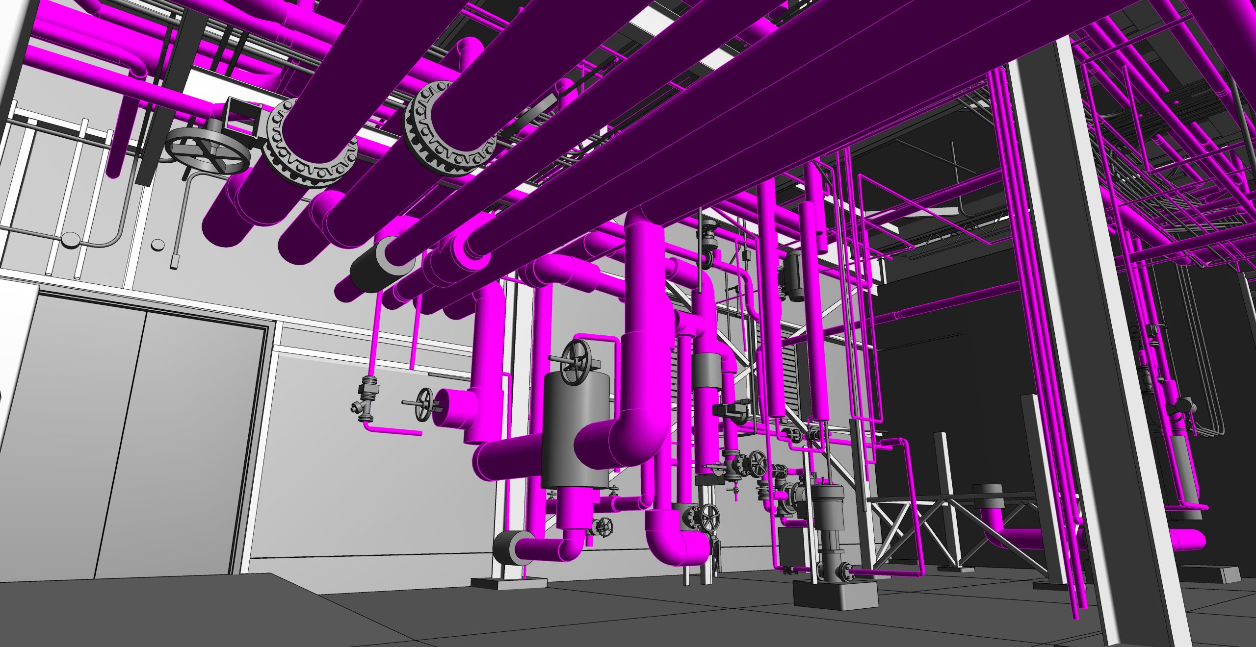
A factory with crowded machine rooms is hard to verify, because one missed valve can hide inside a thicket of pipes. This note describes the workflow used on Project 491.US, a single-floor plant in the United States, and shows how the team kept a dense model honest from the first scan review to the last connection check.
The facility covers 1,900 m². The inputs were a point cloud and site images, and the team worked over two months in March and April 2023. Architecture, structure, topography and MEP were all modeled to LOD 300 and delivered as a Revit file. Our approach to the pipe, duct and cable side of this kind of job is described in our MEP modeling services, which cover how electrical and plumbing systems are reconstructed from scans.
Step 1: cut the plant into zones
The team divided the factory into smaller areas before modeling began. Each zone had its own check, so a mistake in one room did not travel into the next. This also made the review easier to follow, since every reviewer looked at a limited part of the plant.
Step 2: build the backbone, then fill in
Large and well-defined items went in first, namely main pipelines and primary equipment. Smaller components followed, placed around that backbone. The order matters because the big elements give later work a reference to measure against.
Step 3: make the scan readable
Transformer stations and technical rooms produced a lot of noise. Modelers used sectioning, layering and element isolation to see objects that were partly hidden. They switched the cloud to RGB display and raised contrast so the edges of pipes, cables and equipment stood out. Where data was incomplete, experience helped: round, square and rectangular profiles and typical features revealed what each element was.
Step 4: audit every connection
Connections decide whether a model is useful. Flanges, valves, electrical terminations and control links were reviewed with the highest accuracy, because errors there weaken renovation designs and energy or fluid analysis. The full project record is available at Revit modeling for factory in US, including scope, tools and outcomes.
Step 5: confirm against the goals
The last review compared the model with the client's goals: a baseline for renovation and retrofit, a complete MEP model that follows technical standards, and a clear map of gas, chemical and high-power electrical routes.
What the check delivered
The verified model became a centralized 3D database of the plant's MEP system. Maintenance technicians can find a valve or connection point quickly, which shortens troubleshooting and lowers production downtime. Asset teams can plan maintenance with component details in front of them.