
Checking a Dense Hospital MEP Model Against the Scan: A Canadian Case Walkthrough
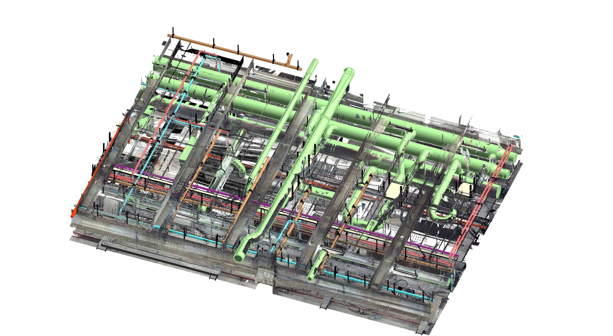
Hospital models rarely fail on the walls. They fail in the ceilings, shafts and plant rooms, where ducts, pipes, conduits and cable trays share the same few square metres. This walkthrough follows how the team on Project 311.CAN approached verification for a three-floor Canadian hospital complex of about 10,000 m², delivered to LOD 300 over two months between December 2021 and January 2022.
The scope was partial. Architecture and structure were modeled as base elements, while the main effort went into mechanical, electrical and plumbing systems. Fourteen specialists worked from a mixed bag of inputs: point cloud scans, Leica Trueview, photographs, videos and existing 2D drawings. Mixed inputs matter because each source answers a different question, and a reviewer has to know which one to trust for which system. Owners who need this kind of operational model often begin with MEP BIM services, since maintenance teams care most about where each system actually runs.
Start with the estimate, not the model
The first check happened before any modeling. MEP input was limited to PDF documents and exterior photographs, so it was hard to judge suspended ceiling positions, object density, the number of service shafts and the layout of each system. The stated aim was a schedule estimate close to the real man-hours, and the limited data made that a genuine risk rather than a formality.
Split the model into zones
For the dense areas, the team segmented the model by zone and used sectional and elevation views for each one. A plan view of a ceiling full of overlapping services tells a reviewer very little. A section through a single shaft shows what sits where, and it cuts confusion before it spreads across the model.
Classify systems before you trust them
HVAC, fire protection, potable and waste water, conduits, cable trays, medical gas and suction or pressure lines overlap in shafts, equipment rooms, basements and corridor ceilings. One easy error is modeling a conduit as a pipe or duct. The team relied on specialists who knew each discipline, because recognition at this density comes from practice as much as from software.
Use photos to settle ventilation questions
The ventilation system was critical, and the point cloud covered the whole exposed ceiling, which made types hard to read. Matching as-built photographs with Leica Trueview annotations let modelers label and attach information with confidence. Custom duct fittings for bends and transitions also helped the model follow the scan more quickly.
Run clashes and QA-QC in layers
Navisworks clash detection ran early so that system conflicts surfaced while they were cheap to fix. Multiple inspection layers followed, with the aim of holding deviation within ±15 mm against actual construction details. After QC, every flagged issue was confirmed as resolved before handover.
What the owner gets
The result is a labeled model of existing MEP conditions that supports maintenance, renovation and later facility management stages, and it reduces the field surveys needed in confined spaces. The full specification block and deliverables are on the page for Revit modeling services for hospital complex at Canada, which lists the inputs, software and scope in one place.