
Checking Automated Scan to BIM Output Before It Reaches a Model
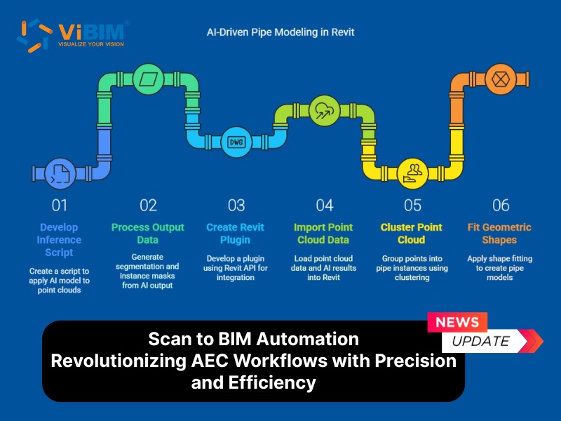
A point cloud rarely arrives in a state where software can turn it into a clean model on its own. The practical question for a delivery team is not whether to use automation, but how to verify what it produces. This note walks through a verification-first way of thinking about an automated workflow, from raw scans to a reviewed Revit model.
The first checkpoint sits before any modeling. Raw data from terrestrial laser scanners or mobile mapping systems has to be cleaned and registered. Automated registration methods such as Iterative Closest Point align overlapping scans, and Statistical Outlier Removal deletes points that sit statistically too far from their neighbors, such as reflections on glass. A modeler still reviews the alignment before anything is built on top of it, because every later error inherits a bad registration.
The second checkpoint comes after segmentation. Deep learning models label each point as wall, floor, ceiling, or window, and geometric fitting then looks for planes and cylinders. Walls, slabs, and straight pipe runs are the elements that this stage handles best. When a team needs a delivery partner to decide which passes to automate and which to model by hand, the scan to BIM services ViBIM provides make that split explicit for each project and run independent quality control on the automated passes.
The third checkpoint is where verification becomes its own automated task. Heatmap deviation analysis compares the generated geometry with the original point cloud and colors the result, with red marking deviation and green marking accuracy. Clash detection scripts then check that newly generated pipes do not intersect existing beams. Neither check replaces a person, but both point the reviewer at the places that need attention first.
Some conditions always send work back to a modeler. Occlusion is the clearest case: if the scanner never saw an element hidden behind furniture or a ceiling, software cannot reliably confirm that it exists. Heritage moldings and custom joinery confuse algorithms trained on standard modern components. Gravity pipes need the correct slope, and that routing logic often needs manual adjustment.
Level of Development decides how much manual work remains. Automation on its own suits LOD 200, which means approximate geometry. Connections, hangers, and fabrication-ready detail at LOD 350 to 400 need significant refinement by skilled modelers. A useful way to put it is that software builds the skeleton and the modeler adds the finish.
For a deeper look at how ViBIM approaches this topic, including its own pipe modeling work in Revit, read the project write-up on scan to BIM automation. It covers the five stages in more detail and lists which tools handle which elements.
A short checklist summarizes the verification mindset:
- Confirm registration before modeling starts.
- Review segmentation labels on a sample of walls, floors, and pipes.
- Run deviation heatmaps against the original scan.
- Run clash detection on generated elements.
- Hand occluded, decorative, and high-LOD areas to a modeler.
Teams that treat automation as a source of draft geometry, and treat verification as the real deliverable, end up with models that match the scan and hold up in coordination.