
Checking a 36,100 m² Site Model Against Its Scan: A Verification Walkthrough
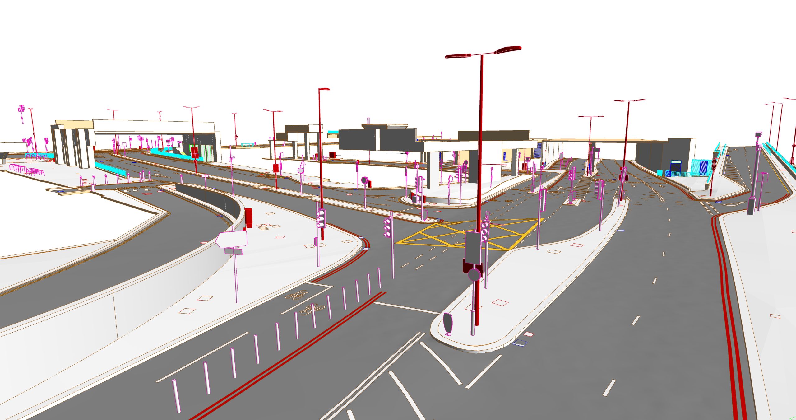
Delivering a Revit model is the easy part. Proving that it matches the ground is where the effort goes. This walkthrough follows the verification path used on Project 380.UK, a single-level UK site of 36,100 m² modeled to LOD 400 between June and July 2022.
The starting point
The team received a point cloud and existing 2D drawings. The client wanted the whole terrain captured, including roads, sidewalks and landscape-related structures, as a baseline for later design and renovation. A full set of 2D drawings also had to come out of the finished model. The strict requirement was a deviation of no more than ±25 mm from the point cloud.
Building in pieces
Checking one enormous surface is painful, so the work began by splitting the site into smaller topographic sections. Each section was modeled and reviewed on its own, which kept Revit fast and made errors easy to locate. Only after the sections passed review were they joined into a single continuous model of terrain and transport network.
Clients who commission a BIM topographical survey for a site of this size usually care about one thing above all: whether the numbers can be trusted when design decisions are made months later. That concern shaped every check below.
Check 1: model against scan
Specialized internal software compared the BIM model with the source point cloud directly. This deviation analysis covers every modeled element, not a sample, and it is the check that confirms the ±25 mm tolerance.
Check 2: structure and composition
The scan tells you where a surface is, but not always what it is made of. Detailed section views in Revit and component inspection software confirmed that the build-up of objects matched the client's architectural and structural requirements.
Check 3: materials
Pavement, grass and sidewalks were modeled with clearly separated materials, so later quantity takeoffs and asset management would work. Where the point cloud could not settle a material, the team compared client-provided site photographs with satellite data from sources like Google Maps.
Check 4: families
The site held many unusual objects, each needing a custom Revit family. A proprietary in-house tool batch-loaded them, which kept the schedule realistic without lowering the detail level.
What the checks produced
The outcome was a definitive as-built model that removes the errors common to manual surveys. You can read the full scope, inputs and deliverables in the case page for Topographic scan to BIM modeling for future design at UK, which lists the specification block in one place.
Why this order works
Segmenting first keeps each review small. Running the scan comparison next catches geometry errors early. Section views and material checks follow, because they only make sense on geometry that is already correct. Families come last, once the surface they sit on is stable.
The same sequence applies to other large sites: split, model, compare, inspect, then hand over a single source of truth.