
From Drawings to a Working Model: How a Team Moves to BIM Step by Step
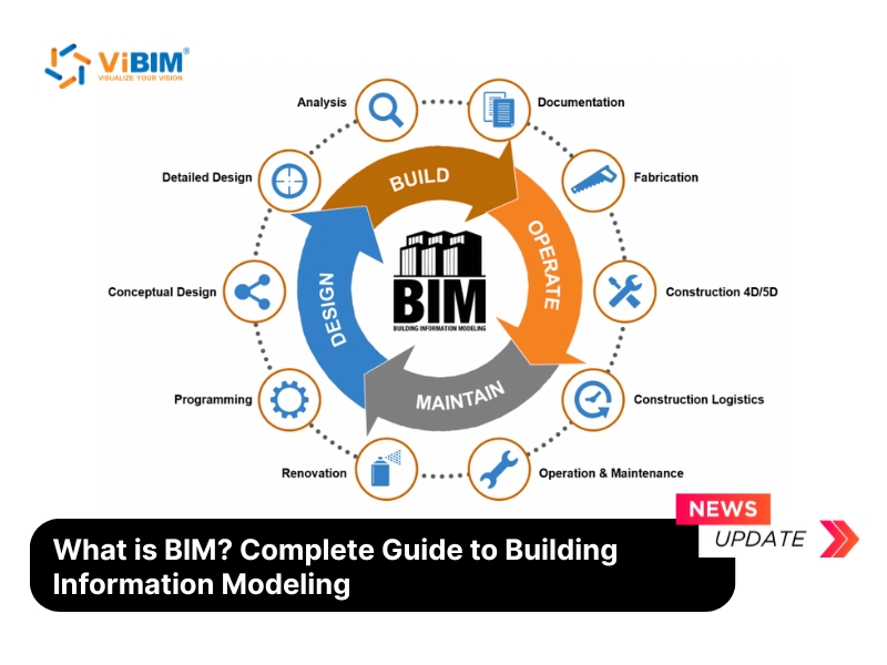
A construction firm usually reaches BIM through a small, practical problem rather than a strategy meeting. A change on one drawing sheet fails to reach the others, a clash shows up on site, or a client asks for data the drawings cannot give. This walk-through follows how such a team gets from that frustration to a model it can trust.
The first step is to separate the idea from the software. BIM is a process in which every object in the model knows what it is, what it is made of and how it relates to its neighbors. Revit, ArchiCAD and Navisworks are the tools that carry that process. Teams that skip this distinction tend to buy licenses first and then wonder why nothing changes. The explanation in our guide on what is BIM covers the five core components behind the process, from 3D geometry to the common data environment.
The second step is to decide what the model must answer. Dimensions help here. A 4D model ties geometry to the schedule, a 5D model adds quantities and cost, and a 6D model brings in energy performance. Alongside that, the level of development tells everyone how far to trust each object, so a field-verified element is treated differently from a design assumption.
The third step is the one that surprises teams working on older buildings. There is no model to start from, so the structure has to be recorded as data first. Laser scanners capture the site as a dense point cloud, and the cloud is measurement rather than geometry. Firms that lack the hardware or the staff often hand this conversion to specialists, and a provider of point cloud modeling services can rebuild those points into parametric elements without the team buying equipment or training from scratch.
The fourth step is verification. Before anyone relies on the model, the team checks it against the scan, then runs clash detection across the federated model to separate hard clashes, such as a beam through a pipe, from soft clashes, such as too little clearance to install a component. Resolving both on screen is far cheaper than finding them with crews waiting.
The last step is a place to keep the result. A common data environment holds the current version of every file, so architects, structural engineers and MEP designers stop working from stale copies. Standards such as ISO 19650 keep naming and exchange consistent, and maturity levels give the team a way to describe progress, from isolated 2D files at Level 0 to one shared cloud model at Level 3.
Teams that follow this order report fewer surprises because each stage answers a question the next one depends on. The model becomes something that the people running the building can still use after handover, not only a design deliverable.