
From Scan to Sign-Off: How a Revit Door Family Gets Built and Checked
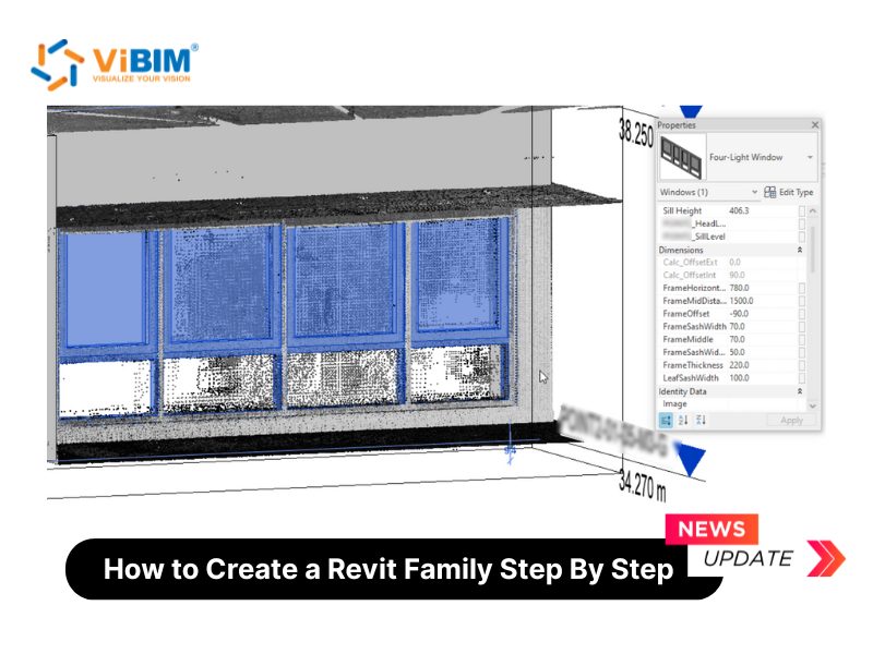
Every as-built Revit door starts with a wall that is not quite what the drawings say. The opening may be a little narrow, the frame may sit off-centre, and the swing may stop short of a return wall. A family built from a catalog size ignores all of that. A family built from the scan keeps it. This note follows one door through the build and the checks that decide whether it can ship.
The first decision is the template. A modeler opens File, New, Family and picks Door.rft for imperial units or Metric Door.rft for metric. That choice sets the category and the hosting behavior, so the door will cut into a wall and show up in door schedules later. Choosing wrong here means a rebuild, because the family will fight the project it lands in.
Next comes the skeleton of reference planes. The modeler draws Rough Width and Rough Height planes around the opening, dimensions them, and clicks EQ so the door stays centered when it flexes. Each plane gets a name such as Left, Right, Head or Sill. Named planes give the geometry something to lock onto. The opening itself is read from the point cloud of the real wall, at 3'-0" by 7'-0" (914 by 2134 mm) in this example, not from a standard size.
With the skeleton in place, the geometry follows in three parts: the opening, the leaf and the frame. The opening is cut by aligning four sketch lines to the planes and locking each with the padlock. The leaf is an extrusion locked to the Height plane. The frame is a sweep along a path around the opening, with a cross-section profile sketched by hand. A locked line flexes with its plane, while an unlocked line drifts, and that single habit separates a parametric family from a static block.
Parameters come after the geometry. A Frame_Thickness length parameter of 2" (51 mm) drives the rough opening through formulas: Rough Width equals Width plus two times Frame_Thickness, and Rough Height equals Height plus Frame_Thickness. Change the width, click Apply, and the opening recalculates. The handle arrives as a nested family, and a formula of Height divided by two keeps it centered on any door size. Materials and a few preset types, such as 30" by 80" (762 by 2032 mm), finish the file.
The verification step is where the work earns its keep. The family is saved as an .rfa, loaded into the project and hosted in the scanned wall. The modeler switches through each preset type, changes an instance parameter and watches for broken geometry. Then the swing is checked in plan against the original point cloud. If the door fouls a return wall in the real space, the model has to show that, not hide it. Many teams that need this kind of scan-matched work look to Revit family creation services once the library grows past what one modeler can check by hand.
Checks continue after sign-off of the geometry. Naming follows a convention and a shared parameter file, so parameters schedule the same way across disciplines. Dimensions and data are held to the level of development and information the deliverable calls for. Every model then passes two independent quality checks before it leaves the team. These steps catch drift between the family and the scan before a client sees it.
The same pattern covers common errors. Wrong category, hard-coded dimensions and a skipped flex test all show up during this sequence, because each step has a check attached to it. A modeler who follows the order rarely meets them late. The full walkthrough, with screenshots for each stage and the three family types explained, is in the ViBIM guide on what is Revit family creation, which covers instance versus type parameters and advanced techniques as well.
The takeaway is simple. A family is only as reliable as the checks behind it. Build from the right template, lock the geometry, drive sizes with parameters, then test in context against the scan. Do those four things in order and the door will schedule, flex and swing the way the building actually stands.